Facebook Pixel Only

Please Wait...

Guidelines for Subwoofers Layouts & Optimal WaveForming™ Performance

An ideal sound system for home cinema must ensure a flat and uniform acoustic response over the entire listening area. A main challenge to achieving this goal resides in controlling the acoustic field at very low frequencies (below 100Hz or so). The acoustic field at these frequencies is strongly dominated by the modal behavior of the room, which introduces large differences between the acoustic pressure across the listening area due to modal maxima and minima. In addition, the many reflections and long decay times of these room modes obscure a great deal of dynamics and detail that might otherwise be experienced and enjoyed.

I. Introduction 


Traditional passive solutions require large volumes of absorption to be effective at low frequency, resulting in an unreasonably large footprint, which is not only expensive in material but also in real estate. Other approaches such as bass traps typically are effective only at specific frequencies and are impractical as a broadband solution. As such, traditional passive acoustic treatments for low frequencies, on their own, are inadequate for home cinema.


In response to this reality, many home theater specialists have adopted multiple subwoofer arrangements in addition to passive treatment. Various arrangements exist and intend to break up modes.  Our research has shown some approaches can indeed mitigate the effect of room modes but do not address the root cause (wave interferences), thereby generating unwanted side effects while not solving the whole problem. 


The exception is the Double Bass Array (DBA) method. The traditional DBA approach, as its name suggests, uses two arrays of subwoofers: one on the front wall (the emitting array) and the other on the rear wall (the absorbing array). The emitting array produces a planar wave to reduce the amount of interference in the room from side wall, ceiling, and floor reflections. Then, the absorbing array attempts to cancel the rear wall reflection with the same signal, but inverted and delayed by the amount of time it takes the sound to travel the length of the room. 

However, this approach provides good results only under ideal conditions, which are difficult to achieve in practice. Too often, the walls are not reflective enough to generate a good planar wave. Also, the wave that reaches the rear wall has changed while traveling the length of the room because the walls are insufficiently stiff or parallel to guide the wave properly… Lastly, the nature of the wave changes as it encounters furniture, risers, tiered seating, etc. As a result, the wave that reaches the rear wall is not the same as the one that left the front wall, and cannot be effectively canceled. To the degree that there is a mismatch, spurious energy is introduced into the room.


Trinnov’s WaveForming™ overcomes existing solutions' limitations, offering a more effective and versatile tool for controlling very low-frequency acoustic fields. The key aspects of WaveForming and some guidelines and recommendations to get the most out of this technology are given below.


Waveforming is a powerful and flexible tool. However, the rules of physics still apply, regardless of the sophistication of the signal processing. 

Specifically, there are two factors that determine the recommended number of subwoofers for any given room:


1.    The size of the front and rear walls. Understandably, larger rooms will require more subwoofers than smaller rooms.
2.    The highest frequency you wish to control. Higher frequencies mean shorter wavelengths which, in turn, require closer spacing of the subwoofers to maintain control over the planar wave formation.  


Please note that this document addresses the number of subwoofers and their recommended placement to maximize the performance of Waveforming. It does not include recommendations on the type of subwoofer to use, nor any recommended technical specifications for each subwoofer. This document also does not include means to calculate the acoustic pressure level of the WaveForming™ system based on each subwoofer’s capability. These recommendations will come in a separate implementation document at a later date. 


The best recommendation at this stage is:

●    Use the same subwoofers within each array.
●    Specify subwoofers with the same bandwidth for both the front and rear arrays.
●    The rear array may consist of subwoofers with less power handling capability than the front subwoofers.

II. Advanced control of low-frequency acoustic waves with WaveForming™


Figure 1 below depicts the working principle of the WaveForming, which consists of two main steps:


1.    In the first step, the acoustic field is evaluated within a volume surrounding and throughout the listening area. The goal of this step is to retrieve the necessary information about the modal behavior of the room (as well as any changes introduced by objects in the room) so that the algorithm can eliminate these unwanted contributions. This is carried out by sampling the acoustic field in a three-dimensional grid of microphone positions throughout the listening area (blue dashed rectangle in Figure 1).

2.    From the acoustic field measured in the previous step, the WaveForming processor calculates the filters to apply to each subwoofer of the system, and applies these filters to eliminate the modal signature of the room. The filters applied to the emitters ensure the generation of the tightest and most uniform wavefront possible within the listening area, while the filters applied to all the subwoofers (including both the front and the rear subwoofer arrays) collectively absorb most of the room reflections and resonances (modes). 


WaveForming’s processing delivers unprecedented performance thanks to its sophistication and capacity to adapt to different constraints (such as irregular subwoofer layouts):

-    Sophisticated: WaveForming combines multiple advanced and unique technologies such as “Acoustic Reshaping,” “Wavefront Synthesis,” and “Multi-Source Multi-Controller optimization” to synthesize a specific filter for each subwoofer in such a way that the entire system works as one idealized subwoofer. WaveForming maximizes the field's homogeneity in time, space, and frequency across the entire listening area. These complex filters overcome the limitations of simple gain-and-delay filters.

-    Adaptable: being calculated from the measured field, these filters adapt to the physical characteristics of each individual room, including the exact shape and acoustic property of each wall and whatever is within the room. Once again, it yields filters far more effective than simple gain-and-delay filters, since they adapt to the specific factors influencing performance in the listening area. This powerful analysis enables a more robust and efficient acoustic field control, even in challenging conditions like non-ideal room geometry.

Figure 1. Working principle of the DBA (left) versus WaveForming (right).

III. Spatial Sampling Guidelines


When the acoustic field is sampled with microphones, the following guidelines are crucial for achieving a good performance.

-    The distance between the front array and the measurement zone should be at least 2 meters.
-    The distance between the measurement zone and the remaining walls and ceiling should be at least 1m
-    The measurement grid should have at least 2 horizontal planes, the first plane being at 1m from the floor (typical ear height for a seated person).
-    The maximum distance between any two adjacent microphone positions should be 1m, so that the acoustic field is unambiguously characterized up to frequencies around 100Hz.

Some precision in the placement of these microphones during the measurement process is important since the WaveForming algorithm needs to have a clear “understanding” of the three-dimensional field throughout the listening area. Objects in the room and even the room itself introduce changes to the wave as it travels the length of the room. These changes need to be documented.


IV. Determining the Number and Placement of Subwoofers


The first questions on everyone’s mind when considering incorporating WaveForming into their room design are 1) “How many subs do I need?” and 2) “How do I position them in the room?”

The answer depends largely on two parameters: 

●    The size of your room (specifically, the dimensions of your front and rear walls)
●    The highest frequency you wish (or need) to control.

It is fairly intuitive that larger rooms might require more subwoofers. But the density of those subwoofers on the wall determines the highest frequency at which a clean, planar wavefront can be created. Both parameters must be decided before an informed decision may be made.

We will tackle these two considerations in reverse order. We believe you will find it easier to understand the requisite number of subwoofers once you better understand the different possible layouts and the flexibility we have in subwoofer placement.  


V. Guidelines for Subwoofer Layouts


This section gives recommendations for optimal subwoofer positioning. These recommendations are derived from extensive research involving numerical simulations, experiments, and theoretical analysis. All experimental data were developed using a specific microphone array that respected the previously described acoustic field spatial sampling guidelines. The following recommendations for subwoofer positioning derive from those data and spatial sampling guidelines.

The layouts employ nomenclature in the form of N_f- N_r, which denotes the number of subwoofers in the front emitting array and the number of speakers in the rear absorbing array.

Figure 2. A 4-4 regular layout (left, top view) and the wall of emitters with their image sources (right, front view).

A. Regular Layouts:  Regular Positions

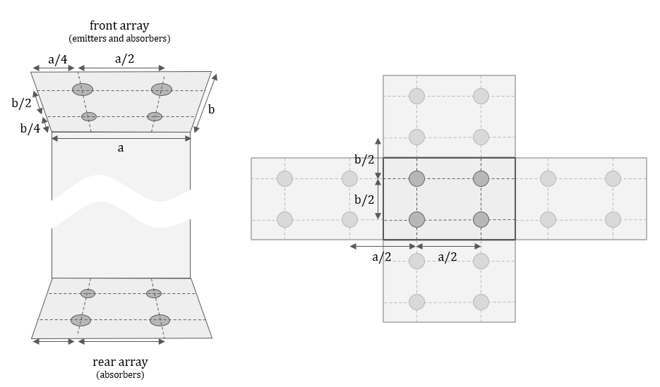
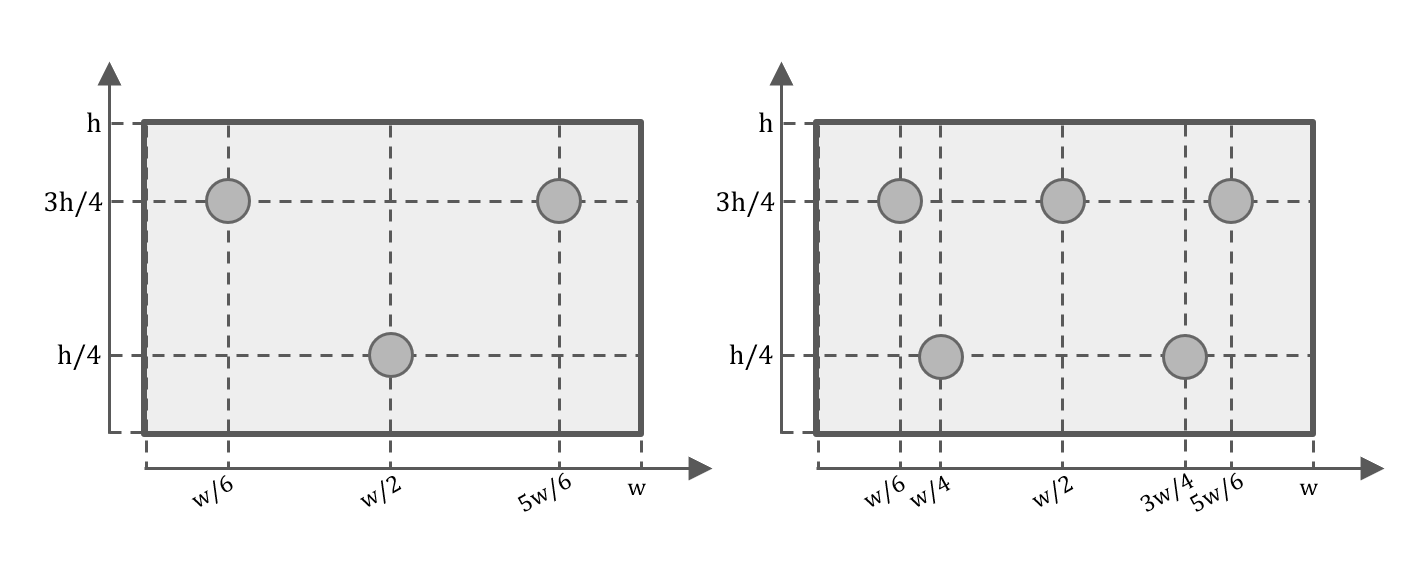
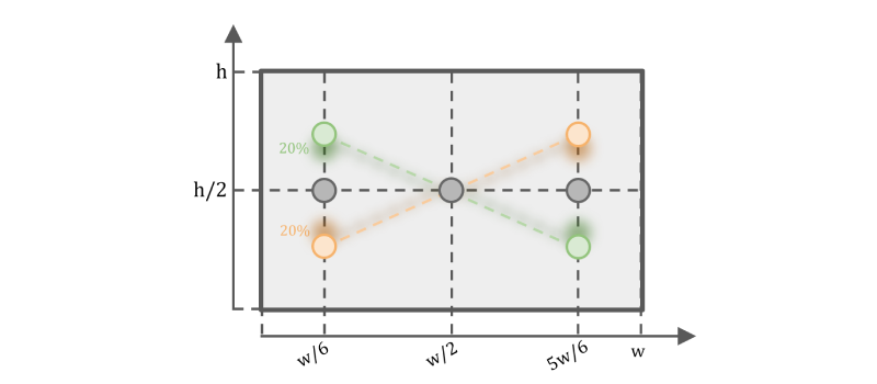
As can be seen in the illustration above (Figure 2), the ideal spacing of the subwoofers is divided up such that the space between a sub and the adjacent room surface (wall, ceiling, or floor) is half of the space between it and its adjacent sub. This spacing ensures that the reflected energy caused by those room surfaces acts as “virtual subs” with equal spacing from the adjacent, actual subs. Ideally, this spacing would hold true both horizontally and vertically. The width of the wall (“a”) is divided by the number of subs along the width of the room, and the height of the wall (“b”) is divided by the number of subs along the height of the room. (In a different room, you might have a 3 x 2 array horizontally and vertically, requiring “a/3” and “b/2” for the spacing.) We call this a “regular layout,” where “regular” refers to the consistency of the layout.


So, in a regular layout, the subwoofers are arranged to have consistent spacing (including those reflections that act as “virtual” subs), both horizontally and vertically. Hence, the distance between a subwoofer on the edge of the array and the adjacent wall must be half the distance between two adjacent subwoofer columns. Similarly, the distance between an “edge” subwoofer and the adjacent ceiling or floor must be half the distance between two adjacent rows of subwoofers. 


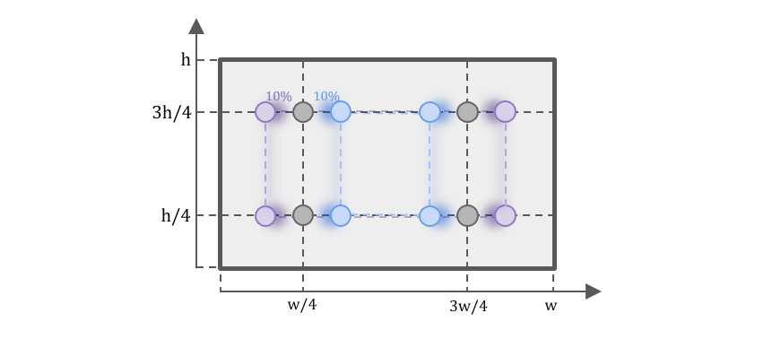
Therefore, if A is the room width and we have C columns of subwoofers, the distance between two adjacent columns is a/C, and the distance from a side subwoofer to its adjacent wall is a/2C. Similarly, for height b and R rows, the distance between two adjacent rows is b/R, and that from the lower/upper row to the floor/ceiling is b/2R. 


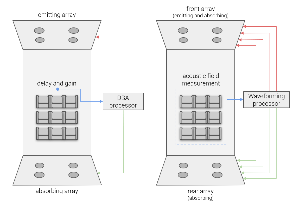
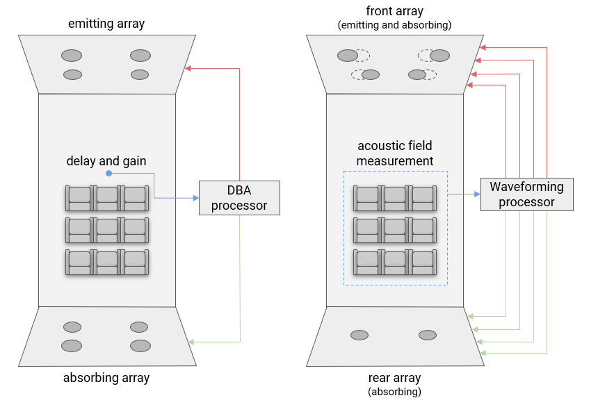
Note that, with WaveForming, the number of front-emitting subwoofers does not have to be equal to the number of rear absorbing subwoofers. The particular layout where the two arrays have the same dimensions and number of subwoofers is known as the Double Bass Array (DBA). Figure 2 shows a 4-4 regular layout with 2×2 arrays in a room of width a and height b.
 

B. Ideal Layouts: Ideal Number of Subwoofers 

The spacing between subwoofers determines the upper-frequency limit that can be effectively controlled as a planar wave. This derives from the fact that higher frequencies have shorter wavelengths and the emitting subwoofers within a certain portion of that wavelength from each other in order for the planar wave formation to work well. (There is no cheating the laws of physics).


The ideal layout is a regular layout in which the arrays have the same dimensions. In such a layout, the positions of the rows and columns of subwoofers are dictated by the room’s height and width, respectively. Furthermore, the distance between two subwoofers determines the optimization’s bandwidth. Therefore, for any given size room, the number of rows and columns determines the upper limit of the controlled bandwidth. 


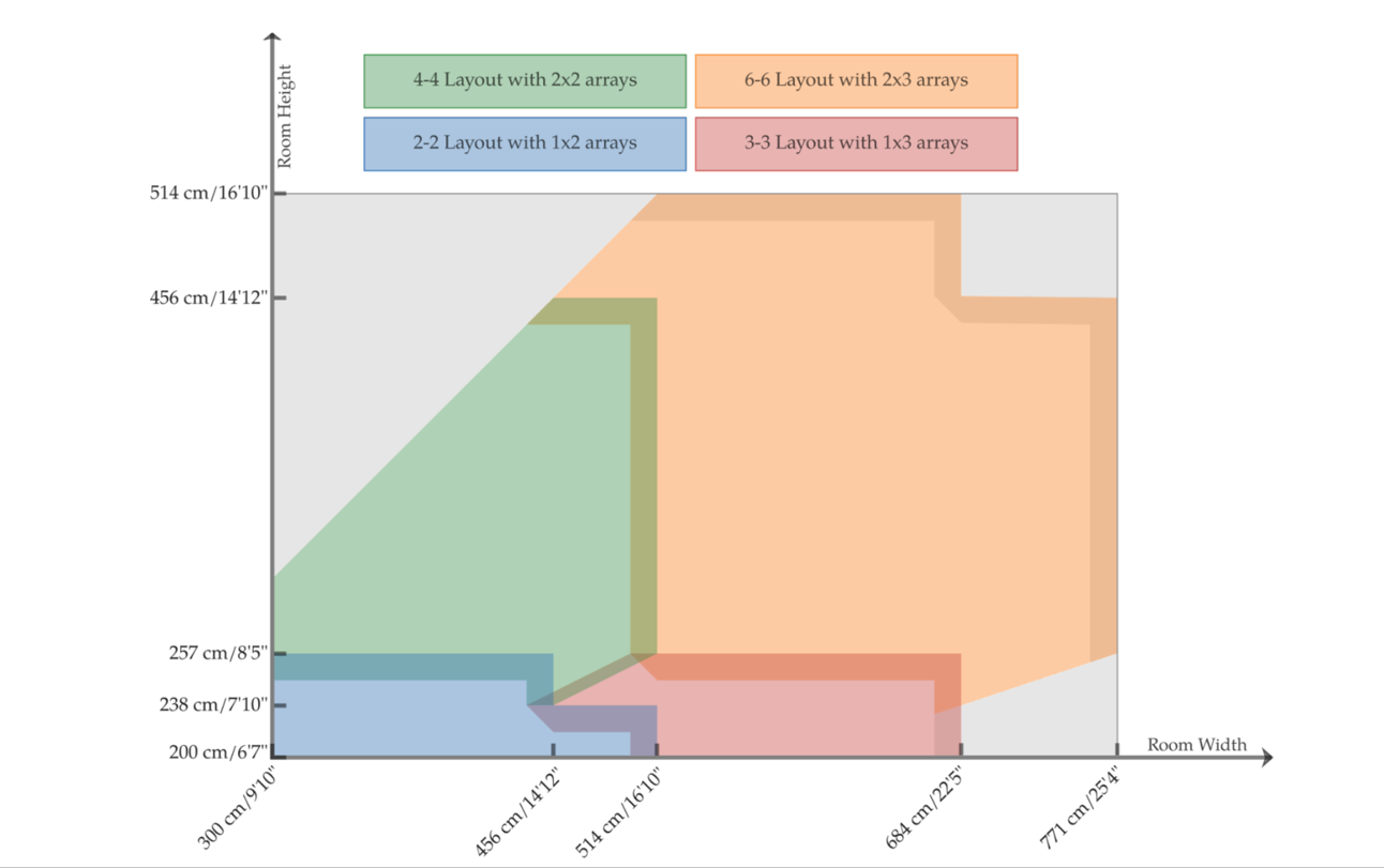
Figure 3 and the following calculator give the number of rows and columns of the ideal layout for a given width and height for a typical bandwidth up to 100Hz. Note that since we propose a discrete output (the number of subwoofers) for a continuous input (the dimensions of a wall), the bandwidth would not be the same for all combinations of room dimensions. Therefore, when at least one of the dimensions is within 15 cm of the limit, the calculator gives a warning, represented by the gray areas in Figure 3.
 

Figure 3. Recommended layouts in terms of room width and height.

The “ideal” layout gives the best performance of WaveForming. That is, having the recommended number of subwoofers (see section IV. C) with equal number of front and rear subs, all in the regular positions (see section IV. B). However, as previously mentioned, the sophistication and adaptability of WaveForming allow it to support a large diversity of layouts while maintaining a high level of performance. In short, it tolerates diverging from the “ideal” layout:


-    Reducing the Number of Subwoofers: the number of subwoofers of the ideal layout, especially the rear subwoofers (absorbers only), can be reduced if required. While this may affect the results,  good performance is expected in all cases. It is preferred to reduce the number of rear subwoofers rather than reducing the number of subs in the front array as the loss in performance is minimal.


-    Support for asymmetric arrays. With Waveforming, the front and the rear arrays don’t need to match, as long as they each remain regular. In that case, the preferred scenario is when the rear array has fewer subwoofers than the front array. Using fewer rear subwoofer does not alter significantly the overall performance, while using fewer front speakers does. This is a simple consequence of the fact that front subwoofers are more important: they are the emitters in addition to also being absorbers. Asymmetric arrays with fewer rear subwoofers can be useful in 2 ways. First, it is an effective way to reduce the number of subwoofers while maintaining a high level of performance. Second, it is a good way to get the best performance for a given number of subwoofers. For instance, with 6 subwoofers, a 4-2 layout will often deliver higher overall performance than a 3-3 layout. And with 8 subwoofers, a 6-2 layout will often deliver higher performance than a 4-4 layout. It is a more general trend than an absolute rule, as each situation depends on the specific room proportions.


-   Support of Irregular Layouts: a certain amount of subwoofer displacement within an array can be tolerated and sometimes even recommended, such as putting 3 subwoofers in an irregular triangle layout. This “wiggle room” is valuable in cases when subwoofer placement options are limited by physical constraints, such as having to work around the Screen speakers. (See Section D for displacement recommendations.)

Figure 1b. Working principle of the DBA (left) versus WaveForming (right) with asymetric and irregular layout.

C. Reducing the Number of Subwoofers & Performance 

Recall that the optimal number of subwoofers for any given room is determined by two factors: the size of the room and the upper frequency that you wish to control. Understandably, larger rooms need more subs for both control and output. But, for any given room size, the spacing between subwoofers determines the upper limit of Waveforming’s ability to create a planar wave.

The following section gives the general guidelines for reducing and/or displacing  the subwoofers, and the corresponding performance levels. 
●    Dark green corresponds to the maximum performance. 
●    Lighter green indicates that the performance may be somewhat reduced .
●    Lightest green is the minimum recommended WaveForming implementation.

However, all the listed layouts guarantee a minimum satisfactory threshold.


The 2-2 Ideal Layout

This is the regular layout with two 1×2 arrays (e.g., one row of two subs on each wall). Since it already has a small number of subwoofers, it cannot be reduced.

The 3-3 Ideal Layout

This is the regular layout with two 1×3 arrays (e.g., one row of three subs on each wall). It tolerates reducing the number of subwoofers by one.

For the reduced layout, the subwoofers are placed in the regular positions (see IV. a).


The 4-4 Ideal Layout

This is the regular layout with two 2×2 arrays (e.g., two rows and two columns of two subs each, on each wall). It tolerates reducing the number of subs by two.

For the reduced layout, the subwoofers should be placed in the regular positions (see IV. a). Reducing to 4-2 is preferred over reducing to 3-3 in the case where the ceiling is too high for having only one row of subwoofers and the room is too narrow for needing three columns.


The 6-6 Ideal Layout

This is the regular layout with two 2×3 arrays (e.g., two rows of three and two columns of two subs on each wall). It tolerates reducing the number of subwoofers from 12 to 8.

In cases 6-4 and 5-4, the four absorbers should be placed in the regular positions (see IV. a). However, it is uncommon to have a room that is wide enough to require three rows of subwoofers while its ceiling is low enough for the processing to perform well. Therefore, when 3 or 5 subwoofers are to be placed on one wall, we recommend positioning them, in this case, as follows: (see Figure 4)

  • 3 subwoofers (irregular triangular layout): one subwoofer at 1/2 of the width and 1/4 of the height (from the floor), and the other two at 1/6 and 5/6 of the width and 3/4 of the height (from the floor).
  • 5 subwoofers (irregular trapezoidal layout): two subwoofers at 1/4 and 3/4 of the width and 1/4 of the height (from the floor) and three subwoofers at 1/6, 1/2, and 5/6 of the width and 3/4 of the height (from the floor).

Figure 4. Irregular layouts with 3 subwoofers and 5 subwoofers

D. Guidelines for Displacing Subwoofers


Common guidelines for all layouts

  1. In general, moving the subwoofers apart is preferred over moving them closer to each other, the worst situation being where all the subwoofers are adjacent (equivalent to having a single acoustic source).
  2. We recommend respecting at least one of the regular position coordinates. In other words, displacements from the regular positions should be performed either horizontally or vertically, but preferably not in both directions simultaneously.


In the rest of this section, horizontal displacement is given as a percentage of the room width and the vertical displacement as a percentage of its height.


Particular cases for the 2-2 layout:

  • Shifting emitters and absorbers in the horizontal direction simultaneously should be avoided. Best performance is obtained when either emitters or absorbers remain at their regular horizontal positions.
  • Emitters and absorbers can be displaced simultaneously in the vertical direction but not exceeding 10%.


Particular cases for the 3-3 layout:

  • If only the center emitter is moved : 
    • horizontally: 15% (Figure 5)

Figure 5. Displacing center emitter horizontally

  • vertically: 30% (Figure 6)

Figure 6. Displacing center emitter vertically

It is better to form triangles or diagonals than shifting all the subs vertically by the same amount:

  • If all emitters are moved vertically: 
    • +/- 5% if all subwoofers moved up or down (Figure 7)

Figure 7. Displacing all 3 emitters vertically

  • +/- 15% if they form a triangle (Figure 8)

Figure 8. Displacing all 3 emitter vertically (triangular layout)

  • +/- 20% if they form a diagonal (Figure 9)

Figure 9. Displacing the side emitters vertically (diagonal layout)

  • If all absorbers are moved vertically, the limits are more flexible: 
    • +/- 10% if all subwoofers moved up or down
    • +/- 30% if they form a triangle
    • +/- 30% if they form a diagonal


Particular cases for the 3-2 layout:

  • If only the center emitter is moved : 
    • horizontally: +/- 15%
    • vertically: +/- 30% 
  • If all emitters are moved vertically: 
    • +/- 15% if all subwoofers moved up or down
    • +/- 20% if they form a triangle
    • +/- 20% if they form a diagonal
  • If the two absorbers are moved vertically: 
    • +/- 10% if all subwoofers moved up or down
    • +/- 20% if they form a diagonal


Particular cases for 4-4 layout:

  • if the emitters are moved (horizontally or vertically): +/- 10% (Figures 10 and 11)

Figure 10. Displacing all 4 emitters horizontally

Figure 11. Displacing all 4 emitters vertically

  • if the absorbers are moved (horizontally or vertically): +/- 15%
  • it is preferred to move the subs apart from each other than to move them closer to each other or to move all of them in one direction.


  • If the listening area is far enough from the ceiling (in other words, if the sampling zone is closer to the floor than to the ceiling), then moving the subwoofers into a trapezoidal layout is preferred.* (Figure 12)

Figure 12. Displacing all 4 emitters horizontally (trapezoidal layout)

* That is, moving the top subs away from each other and the bottom subs closer to each other or vice-versa.

VI. Conclusions


Trinnov was incorporated twenty years ago to do fundamental research into how we humans perceive complex, three-dimensional sound fields. Much of the early research centered around the possibility of capturing such a sound field in, say, a concert venue, with an eye toward reproducing the same sound field in a much smaller room (in your home). In fact, our Optimizer technology was developed as a direct result of that early research.
 

However, there was much more to be learned regarding low frequencies and their interactions with those same small rooms (meaning, residentially-sized rooms rather than concert halls or sports stadiums). Although many scientists and engineers have worked on the problem, most of that work resulted in ways to mitigate the problems found at those frequencies.
 

We set out to learn whether there was a way to eliminate those same concerns.
 

During our research, we learned a great deal about the complex workings of low frequencies in small rooms. We expect it may take five or even ten years to implement technologies that will have sprung from that research. In short, there is much more to come.
 

However, we expect that the highest and best implementations of what we have learned will always have some resemblance to the traditional Double Bass Array (DBA). WaveForming makes such designs vastly more flexible and effective by introducing a great deal of embedded “intelligence” in its sophisticated algorithms. Hence our decision to introduce the best implementation of WaveForming first: we wish to demonstrate what is now possible thanks to this years-long research project.
 

This is only the beginning of WaveForming’s technological release. We plan to expand the scope of capabilities made possible by what we have learned, including new features that will apply both to these front-and-rear bass arrays as well as other, less demanding system designs. The powerful PC-based signal processing made possible by our unique hardware platform allows us to develop and deliver these features to our customers via simple software updates, validating our decision all those years ago to take the road less traveled.
 

We hope you have found this short white paper interesting and educational. We look forward to helping people discover the world of low-frequency dynamics and detail that is uncovered when you eliminate the cacophony of bass reflections and resulting modal problems that normally dominate low-frequency reproduction in the home.

Sign up For Trinnov News

Sign up for our newsletter here. See our Privacy Policy

Subscribe